Download Templates for Project Management | FREE Upgrades & Additions
Author: Mark Whitfield
Welcome to my site!
After graduating in Computing in 1990, I accepted a position as a programmer at a Runcorn based software house specialising in electronic banking software, namely sp/ARCHITECT-BANK on Tandem Computers (now HPE NonStop). This was before the internet became more prevalent and so the notion of enabling desktop access to company accounts for inter-account transfers and book keeping was still quite a cutting edge idea (and smartphones only ever hinted at in Space 1999). The company was called The Software Partnership (which was taken over by Deluxe Data in 1994).
I spent 5 years in Runcorn developing code for SP/ARCHITECT for various banks like TSB, Bank of Scotland, Rabobank and Girofon (Denmark) to name but a few. I then moved onto a software house in Salford Quays for further bank facing projects. After a further 23 years in the IT industry and now a Senior IT Project Manager (both Agile and Waterfall delivery), I thought I would echo out my Career Profile in this corner of the internet for quick and easy access.
Agile Scrum Master’s Checklist for Program Increment
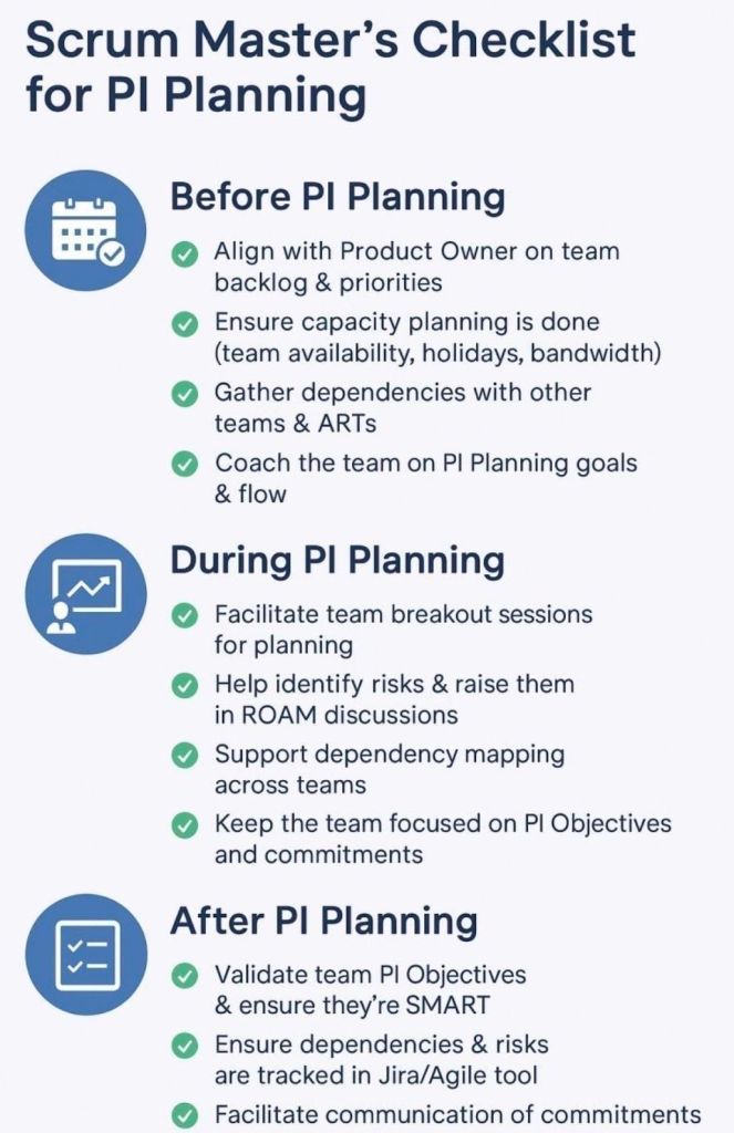
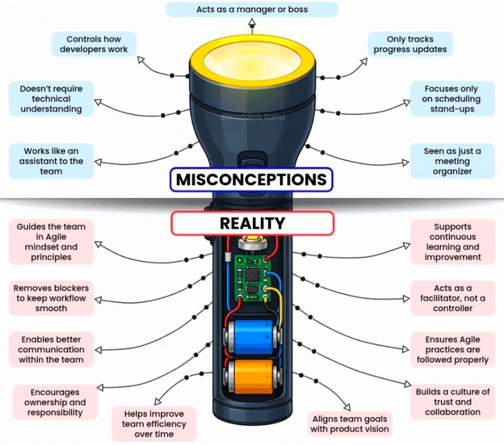
An Agile Scrum Master’s checklist for a Program Increment (PI)ensures your team is aligned, dependencies are resolved, and a realistic delivery plan is established for the upcoming 8–12 weeks of work. As a facilitator and coach, you support the team across three core phases: Pre-PI Planning, During PI Planning Events, and Post-PI Execution.
Here is a comprehensive checklist structured across the lifecycle of a Program Increment.
📅 Phase 1: Pre-PI Planning Readiness
Establish Sprint Cadence: Define exact start/end dates for every sprint within the upcoming PI.
Calculate Team Capacity: Factor in vacations, public holidays, corporate events, and historic team velocity.
Refine the Backlog: Collaborate with the Product Owner to ensure top features meet the Definition of Ready (DoR).
Encourage Feature Decomposition: Guide developers to begin breaking down high-priority features into draft user stories.
Prepare Digital Tooling: Set up virtual whiteboards like Miro or MURAL, and structure project boards in systems like Jira.
Align Engineering Standards: Review architectural patterns with system architects to prevent technical blockers.
🛠️ Phase 2: During the PI Planning Event
Day 1 Breakout Management: Facilitate your team’s breakdown of features into actionable, estimated sprint user stories.
Map Dependencies: Identify files, data, or logic needed from external teams and link them on the program board.
Draft PI Objectives: Help the team write clear, outcome-oriented, and SMART goals based on their planned work.
Surface Program Risks: Collaboratively categorize all technical or resource hurdles using the ROAM framework (Resolved, Owned, Accepted, Mitigated).
Day 2 Plan Finalization: Ensure uncommitted objectives are preserved for high-risk items requiring external prerequisites.
Conduct Confidence Votes: Run an anonymous digital vote to gauge psychological safety and realistic alignment before final team commitment.
🚀 Phase 3: Post-PI & Execution Tracking
Sync the Agile Tooling: Move sticky notes and analog mappings directly into active Jira epics or tracking backlogs.
Establish Sprint Tracking: Distribute automated calendar sequences for recurring Daily Scrums, Sprint Plannings, and Sprint Reviews.
Monitor Cross-Team Risks: Attend standard Scrum of Scrums (SoS) meetings to report on blockers and coordinate incoming dependency tracks.
Protect the WIP Limits: Enforce explicitly defined work-in-progress (WIP) boundaries to prevent team burnout over mid-increment changes.
Inspect and Adapt (I&A): Facilitate the final evaluation comparing actual value delivered against initial PI targets to feed process enhancements back into the train.
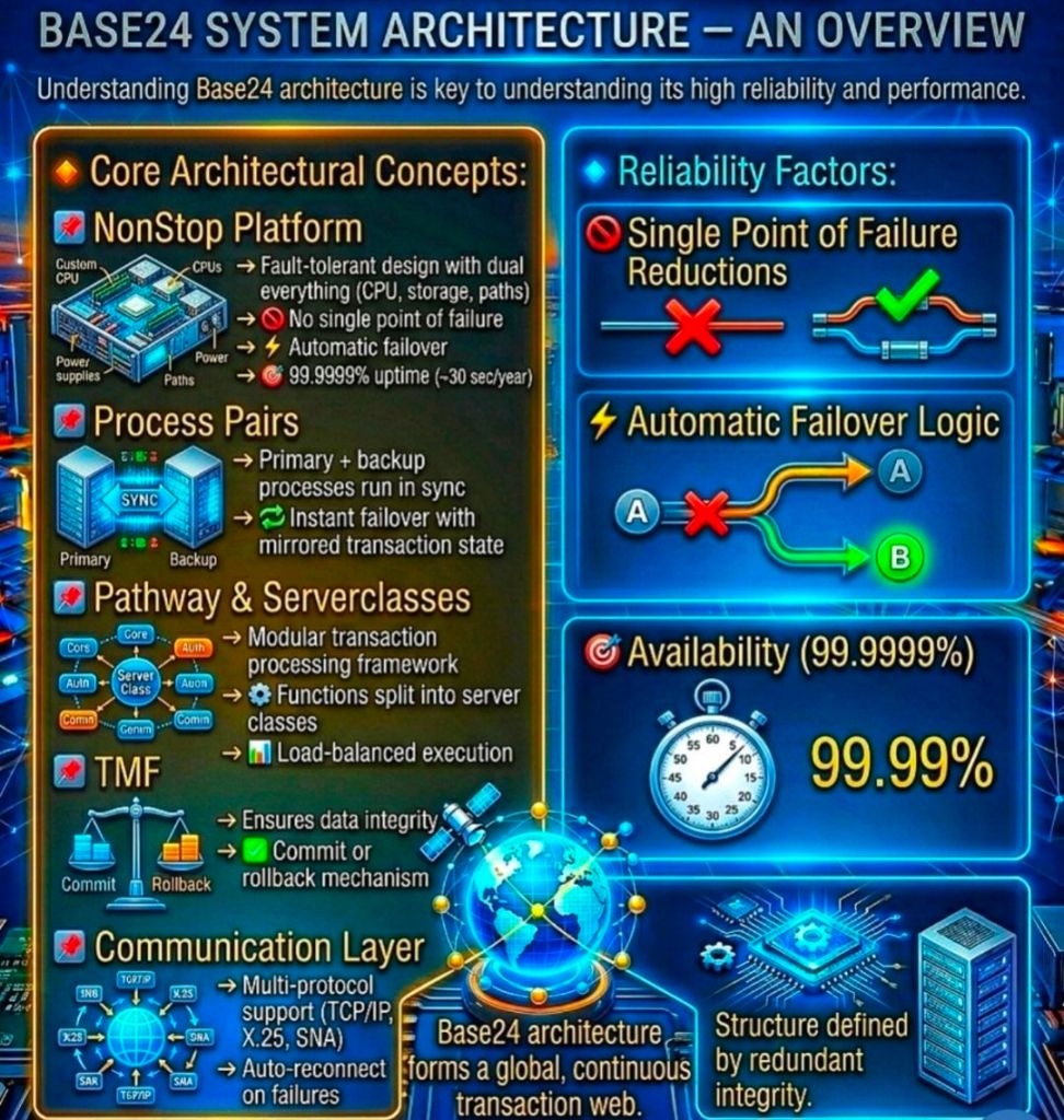
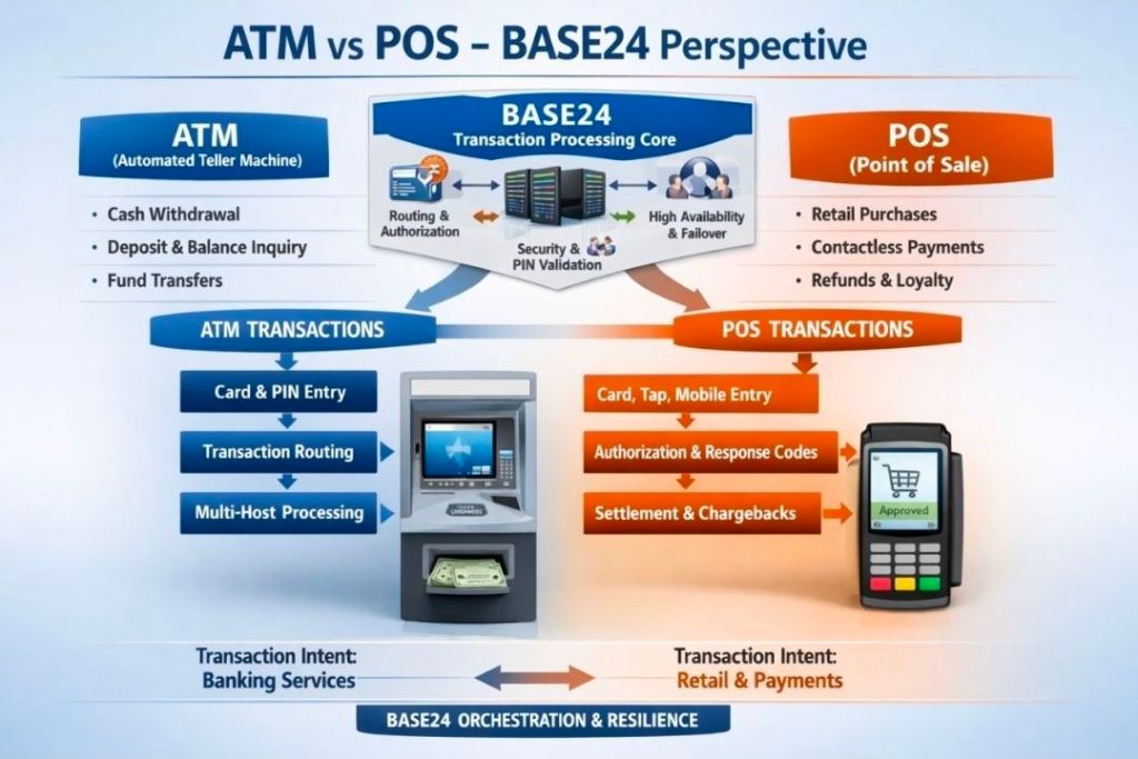
BASE24 is a market-leading, fault-tolerant Electronic Funds Transfer (EFT) software application developed by ACI Worldwide. For decades, it has served as the backbone for global banking, processing billions of ATM, Point of Sale (POS), and smart card transactions.
BASE24 Electronic Funds Transfer (EFT) software application developed by ACI Worldwide, Overview
The product achieves its landmark 24/7/365 uptime by running natively on the HPE NonStop architecture—originally engineered by Tandem Computers.
1. Underlying Technology Stack
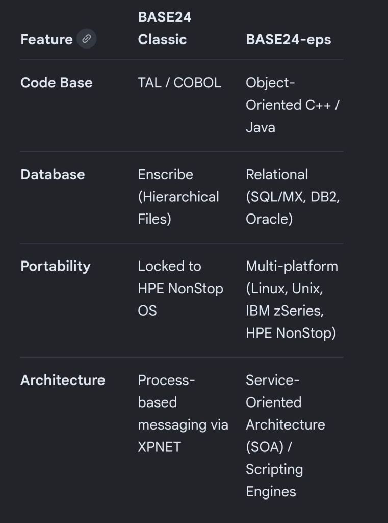
BASE24 Classic was built from the ground up to utilize the unique properties of the Tandem/HPE NonStop platform:
Database:Enscribe, a native hierarchical/flat file database optimized for ultra-fast, unstructured file access. Newer iterations use NonStop SQL/MX.
Programming Languages: Primarily TAL (Tandem Application Language), pTAL, and COBOL/SCOBOL.
Middleware:PATHWAY (PATHCOM), which acts as the transaction processing monitor to dynamically manage and load-balance server processes.
2. High-Level Component Architecture
BASE24 relies on an interconnected network of specialized processes that route and manage messages.
A. XPNET (The Networking Engine)
XPNET is a critical, proprietary communication subsystem. It provides the messaging infrastructure where applications interface with network communication lines. XPNET acts as the buffer layer, monitoring physical lines, enforcing transaction timing checks, and distributing data loads uniformly across CPUs.
B. Device Handlers (DH)
Device Handlers act as the translators for peripheral devices.
Function: They intercept hardware-specific protocol messages (e.g., Diebold or NCR formats from ATMs) and normalize them into BASE24’s internal standard message format.
Security: DH processes handle terminal-level PIN encryption, coordinate MAC (Message Authentication Code) keys, and initiate terminal downline loads.
C. Authorization Process (AUTH)
AUTH is the core decision engine of the application.
Function: It validates card restrictions, tracks card usage accumulations, and performs transaction risk checks.
Fallback Management: If a bank’s core system goes offline, AUTH drops into “Stand-Alone” or “Negative/Parametric Authorization” mode, approving transactions locally up to safe, pre-defined limits.
D. Host Interfaces (HI)
The Host Interface connects BASE24 to the financial institution’s primary backend core banking systems. It handles “On-Us” transactions—meaning the card used belongs to the bank owning the terminal.
E. Interchange Interfaces (II)
The Interchange Interface formats, translates, and routes transactions to global credit/debit networks (such as Visa, Mastercard, AMEX) or regional switches. It transforms internal BASE24 data formats into compliance standard formatting, such as ISO 8583. It handles “Not-On-Us” transactions.
3. Core Database & File Structure
BASE24 captures system activities across specialized transactional and tracking files, mostly utilizing Enscribe:
TLF (Transaction Log File): The primary log capturing every ATM event, amount, response code, and terminal ID in real-time.
PTLF (POS Transaction Log File): Mirrors the utility of the TLF, but optimizes records strictly for merchant POS transactions.
LCONF (Logical Network Configuration File): Dictates how network configurations, devices, institutions, and communication paths map into XPNET.
CAF (Cardholder Authorization File): Stores specific card numbers, limits, and statuses used for stand-alone authorization if host links break down.
4. Daily Operational Processes
Beyond live message switching, BASE24 executes several critical back-office operations:
Extract: Periodically filters transaction data from live TLF/PTLF logs to move to external billing arrays.
Refresh: Downloads updated data dumps (such as blacklisted cards or updated balances) from core hosts into local BASE24 database files.
Settlement Initiator: Aggregates transaction volumes at specified cutoff times to reconcile balanced records between ATMs, POS terminals, and clearing networks.
5. Why Tandem/HPE NonStop is Essential to BASE24
BASE24 relies on the hardware/software synergy provided by HPE NonStop to achieve near-zero downtime:
Shared-Nothing Architecture: Processors operate independently with their own memory stacks. If a physical CPU suffers hardware failure, it cannot corrupt the rest of the application.
Process Pairs: BASE24 components operate via a primary process in one CPU and a backup process in an alternate CPU. The primary constantly syncs checkpoint data with its backup. If the primary drops, the backup assumes processing instantly without interrupting transaction flights.
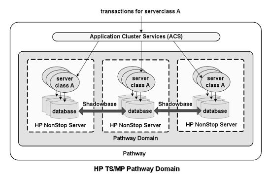
Active/Active Configuration: Utilizing replication software like HPE Shadowbase or DRNet, financial firms link distinct geographic NonStop locations. Both processing sites operate concurrently, managing localized transactions and replicating states reciprocally.
6. Product Evolution: BASE24 Classic vs. BASE24-eps
ACI Worldwide evolved the platform from BASE24 Classic into BASE24-eps (Enterprise Payment System):
Product Evolution: BASE24 Classic vs. BASE24-eps
BASE24 Electronic Funds Transfer (EFT) software application developed by ACI Worldwide, Overview
BASE24 Electronic Funds Transfer (EFT) software application developed by ACI Worldwide, Overview
The HPE NonStop architecture (originally engineered by Tandem Computers in 1976) is a specialized, 100% fault-tolerant computing platform designed to achieve continuous application availability and absolute data integrity. Unlike traditional mainframes or high-availability clusters that rely on rapid rebooting or switching resources upon a crash, NonStop prevents downtime entirely by masking failures through a hardware-software co-designed shared-nothing architecture.
At the physical tier, a NonStop system is built as a Loosely Coupled Multiprocessing (LCM) environment.
Independent Processor Modules: A single system consists of 2 to 16 independent CPUs (expandable via clustering up to 4,000+ CPUs). Each processor module contains its own dedicated Intel Xeon cores, memory, and I/O logic. Processors share no main memory, buses, or execution states. This isolation guarantees that a memory corruption or hardware crash in one CPU cannot physically propagate to another.
The Interconnect Fabric (ServerNet / RoCE): Because CPUs share nothing, they cooperate entirely by passing high-speed messages. Historically, this handled via a proprietary dual-bus named Dynabus, which evolved into ServerNet (the foundational grandfather of InfiniBand). Modern HPE NonStop X systems leverage RDMA over Converged Ethernet (RoCE) as the multi-gigabit interconnect fabric, providing dual-path, point-to-point messaging with sub-microsecond latency.
Dual-Ported, Redundant I/O Controllers: Every storage device, network interface, and controller card is physically dual-ported and cross-connected to two separate processor modules. If Processor A fails, Processor B seamlessly accesses the disk or network line using the alternate hardware path.
No-Spare, Active-Active Components: Every active element operates under a “no-spare” philosophy. Power supplies, cooling fans, and storage arrays are fully redundant and hot-swappable, ensuring the system can be repaired or upgraded while fully operational.
2. Operating System Architecture: NonStop OS (Guardian)
The foundational operating system is NonStop OS, which embeds the Guardian Kernel.
Distributed Copy Model: Every individual processor module loads and runs its own separate copy of the Guardian kernel. Rather than a monolithic OS orchestrating all chips, the system runs as a highly cooperative, message-driven distributed microkernel OS.
The Message System: The core of Guardian is its message router. Every operational request—whether writing a line to a database, opening a network socket, or checking a disk—is written as an inter-process message sent across the RoCE fabric. If a local resource is occupied, the message router redirects the request transparently across the fabric, making the entire cluster appear to applications as a single system image (SSI).
Continuous Heartbeats: All components and processors continually broadcast periodic “alive” heartbeat messages to one another. If a processor fails to respond to a heartbeat within a few milliseconds, the remaining CPUs immediately sever ties with it, declare it dead, and safely re-route pending workloads.
3. Software Fault Tolerance: Process Pairing
Hardware isolation is only half the battle. To tolerate software failures without dropping transactions, NonStop utilizes Process Pairs.
Primary and Backup Processes: When a critical application or system service starts, it creates two instances: a Primary Process executing on Processor 1, and a Hot-Standby Backup Process residing on Processor 2.
Real-Time Checkpointing: As the primary process performs work (e.g., executing a financial transaction step), it sends regular checkpoint messages to the backup process. These checkpoints copy vital state changes, register values, and memory updates.
Instant Takeover: If Processor 1 crashes, the Guardian OS instantly promotes the backup process to Primary. Because the backup contains the mirror state of the last transaction checkpoint, it picks up execution precisely where the failed process stopped. No state is lost, no connections drop, and the end-user experiences zero interruption.
4. Database & Storage Architecture: Enscribe, NonStop SQL, and TMF
Data integrity is paramount in NonStop’s design. It enforces strict ACID compliance at massive scale through layered data management software.
Enscribe & NonStop SQL/MX: NonStop supports Enscribe (a highly resilient structured file system) and NonStop SQL/MX (an ANSI-compliant relational database management system). Both are entirely decentralized, natively distributing table partitions across different physical disk drives managed by separate CPUs.
Mirrored Disks: Storage volumes are configured via volume-level mirroring (Disk 1 and Disk 2 track identical data blocks). Disk writes are executed in parallel across distinct I/O paths. If a drive fails or a sector corrupts, reads are immediately diverted to the mirror disc.
Transaction Monitoring Facility (TMF): TMF is the protected transaction manager. It acts as a distributed two-phase commit coordinator. If an application crashes mid-transaction, or an entire processing module loses power, TMF uses audit logs to back out incomplete transactions cleanly, guaranteeing that the database is never left in an inconsistent or corrupt state.
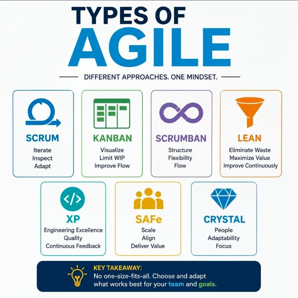
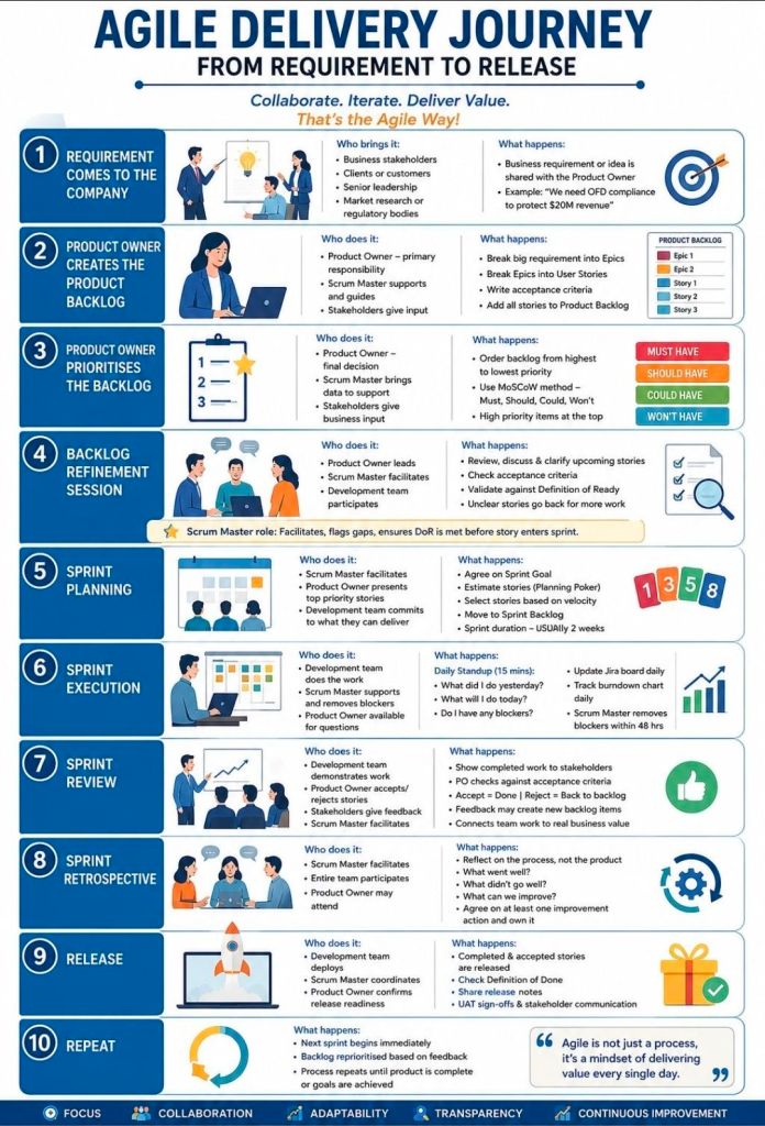
Agile delivery is an iterative approach to project management that focuses on delivering value early, frequently adapting to change, and maintaining continuous customer feedback. Rather than executing a project sequentially, teams break work into small increments to maximize flexibility and product quality.
The most common types and frameworks of agile delivery include the following structured methodologies:
1. Scrum
Scrum is the most widely used agile framework, characterized by highly structured, time-boxed iterations called Sprints (typically 1 to 4 weeks long).
Key Concept: Teams work toward a single, actionable goal during each sprint.
Key Roles: Product Owner (represents the customer), Scrum Master (removes obstacles and enforces the framework), and Developers.
Best For: Projects where requirements change frequently and close collaboration with clients is required.
2. Kanban
Kanban is a visual workflow management system that emphasizes continuous delivery and transparency without strict time-boxed iterations.
Key Concept: Work is tracked on a Kanban board divided into columns (e.g., “To Do,” “In Progress,” “Done”).
Key Roles: Self-organizing teams with a pull-based approach.
Best For: Operational workflows, support/maintenance teams, and organizations that need to limit “work in progress” (WIP) to prevent bottlenecks.
3. Lean Software Development
Adapted from Toyota’s lean manufacturing principles, Lean focuses on maximizing customer value while minimizing waste.
Key Concept: Focuses on “eliminating waste” (anything that doesn’t add value to the end user), amplifying learning, and delivering as fast as possible.
Best For: Optimizing overall organizational workflows and reducing overhead.
4. Extreme Programming (XP)
XP focuses heavily on technical excellence and software engineering practices to boost product quality and responsiveness.
Key Concept: Uses practices like pair programming, test-driven development (TDD), and continuous integration.
Best For: Development teams that need to release updates frequently while maintaining strict quality and low bug rates.
5. Feature-Driven Development (FDD)
FDD is a model-driven approach that is highly structured and focuses on building software in short, feature-by-feature iterations.
Key Concept: Work revolves around creating detailed software models and planning by specific features, which are built one by one.
Best For: Teams that prefer structured, step-by-step processes or environments with traditional hierarchical structures.
6. Scaled Agile Framework (SAFe)
SAFe is designed for larger enterprises that need to align cross-functional, multiple Agile teams toward a single business strategy.
Key Concept: Blends Lean, Agile, and DevOps principles to coordinate alignment, governance, and delivery across a massive scale.
Best For: Large organizations and complex projects requiring multiple teams to coordinate efforts.
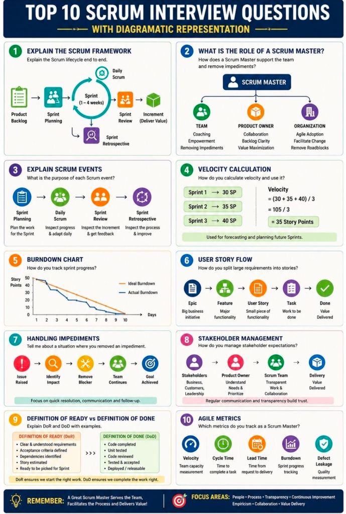
Preparing for an Agile Scrum interview requires a mix of theoretical knowledge, situational problem-solving, and a clear understanding of your specific role (Scrum Master, Product Owner, or Developer). Be ready to discuss the Scrum framework, roles, artifacts, ceremonies, and how you foster self-organization and continuous improvement.
Review these common Agile Scrum interview questions, categorized by topic:
1. Fundamentals & Frameworks
What is the difference between Agile and Scrum? Agile is an overarching project management philosophy focused on iterative development and flexibility. Scrum is a specific, lightweight framework within Agile that uses set roles, artifacts, and timeboxed “sprints” (usually 1-4 weeks).
What are the core roles on a Scrum Team? The three primary roles are the Product Owner (maximizes value, owns the backlog), the Scrum Master (servant-leader, removes impediments, ensures Scrum rules are followed), and the Developers (cross-functional team that delivers the increment).
What is a “Spike”? A spike is a timeboxed research or exploration task used to reduce uncertainty, figure out a technical approach, or better understand a requirement before development begins.
2. Scrum Ceremonies (Events)
What happens during a Sprint Planning meeting? The team collaborates to determine what work can be delivered in the upcoming sprint and creates a plan (the Sprint Backlog) for how to achieve this Product Goal.
Can you give a 2-3 minute overview of the Daily Scrum? It is a 15-minute timeboxed event for the Developers to inspect progress toward the Sprint Goal and adapt the upcoming work. It is not a status report to management; it is for the team to synchronize and plan the next 24 hours.
What is the purpose of a Sprint Retrospective? Held at the end of every sprint, the team inspects the past sprint regarding people, relationships, processes, and tools. The goal is to identify what went well and create a plan for implementing improvements.
What is the difference between a Sprint Review and a Retrospective? The Review inspects the software/product increment to adapt the Product Backlog. The Retrospective inspects the team’s process and working environment.
3. Artifacts & Estimation
What is the Definition of Done (DoD)? It is a shared, clear checklist of criteria that must be met for a product increment to be considered ready for release. It ensures consistency and quality across the team.
What is Velocity? Velocity measures the total amount of work (usually in Story Points) a Scrum Team can deliver during a single sprint. It is typically calculated as an average over the last 3-4 sprints and helps predict future delivery.
How do you handle scope creep? Emphasize that in Scrum, the sprint scope is locked once the sprint starts. If new work is urgent, it should go to the Product Backlog for future planning, or the team can negotiate with the Product Owner to remove an equally sized task from the current sprint to make room.
What do you do if a manager tries to dictate or assign tasks to the team? Coach the manager on Scrum principles (self-management) and act as a shield to protect the team from outside interference, allowing them to focus on the Sprint Goal.
How do you build trust with your team? Focus on empathy, transparency, consistency, and active listening. Build a safe space where the team can fail forward, experiment, and voice concerns without fear of retaliation.
How do you handle conflict within the team? Encourage the team to resolve conflicts themselves first, stepping in only if it affects the sprint goals. Facilitate open dialogue focusing on the issue (the process/problem), not the person.
The development of programming languages on the HPE NonStop platform (originally founded as Tandem Computers) is tightly bound to its architectural hardware transitions: from custom CISC stack machines to MIPS RISC, Intel Itanium, and eventually standard Intel x86-64 infrastructures.
Detailed List of NonStop Programming Languages
1. Core Proprietary & System Languages
TAL (Transaction Application Language): The foundational system programming language for Tandem. It is a block-structured, machine-dependent procedural language designed to compile directly into highly efficient machine instructions. It features ALGOL/Pascal-like syntax but implements C-like semantics, structural pointers, and weak data typing.
pTAL & epTAL: Specialized evolutions of TAL. Rather than rewriting legacy codebases from scratch during architecture shifts, pTAL was introduced to compile existing TAL code natively into MIPS RISC architectures. Later, epTAL was developed to target Intel Itanium microprocessors.
TACL (Tandem Advanced Command Language): A built-in command interpreter and interpreted scripting language. It functions like a Unix Bash shell but features highly complex macro capacities used to orchestrate system configurations, monitor processes, and automate failover procedures.
2. Enterprise & Enterprise Legacy Languages
COBOL85 (and older COBOL74): The undisputed workhorse of NonStop commercial workloads. HPE’s tailored implementation of the COBOL85 standard natively interfaces with the Guardian OS. It allows programmers to embed SQL/MP statements and program fault-tolerant Process Pairs through HPE NonStop Pathway (TS/MP).
SCOBOL (Screen COBOL): A specialized, high-level structural derivative of COBOL utilized exclusively to build blocks for character-cell terminal interfaces (such as the 6530 terminal environments) running within Pathway architectures.
NonStop SQL (SQL/MP and SQL/MX): While technically a database system, its embedded syntax acts as a declarative language integrated into C and COBOL. SQL/MP works with the legacy Guardian file system, while SQL/MX brings ANSI-compliant SQL closely bound with the Open System Services (OSS) environment.
3. Standard Mainstream Languages
C & C++: Heavily introduced during the RISC transition to allow software portability. Mainstream development on modern NonStop systems uses standard C/C++ cross-compilers. They run in either the native fault-tolerant Guardian personality or the standard POSIX-compliant Open System Services (OSS) environment.
Java: A first-class language layer deployed natively on NonStop. HPE optimizes the Java Virtual Machine (JVM) to scale across multi-CPU shared-nothing frameworks, allowing modern enterprise web apps to run with out-of-the-box system availability.
4. Modern Open-Source Options
Python, Go, & JavaScript (Node.js): Modern procedural and script utilities provided by HPE. These environments leverage the OSS POSIX platform layer, running modern DevOps orchestration, microservices, and hybrid-cloud pipelines alongside the native database engines.
Detailed Timeline Breakdown by Era and Year
The evolution of NonStop languages maps directly across distinct engineering ownership eras.
The Proprietary Foundation Era (Tandem Computers: 1974–1989)
1976: Tandem ships the original Tandem/16 (NonStop I). TAL is the only available language on the platform. The entire Guardian Operating System is written completely in TAL.
1981: The NonStop II hardware is introduced. Tandem expands language support to include COBOL74, FORTRAN, and BASIC to attract mainstream banking clients.
1983: Tandem releases the Transaction Monitoring Facility (TMF) and Pathway application management software. SCOBOL is introduced alongside them to program secure terminal entry interfaces.
1985: TACL is deployed, completely modernizing the command line shell ecosystem with scalable macros and structured operational control.
1986: Tandem launches NonStop SQL, the first linearly scalable, fault-tolerant relational database engine. Embedded SQL syntax is integrated directly into TAL and COBOL compilers.
1988: Compilers undergo a major update to natively support the newly established COBOL85 standard, which quickly replaces COBOL74 for all mission-critical banking transactions.
The Open Systems & Hardware Transition Era (Compaq: 1990–2001)
1991: Hardware migrates from CISC stacks to MIPS RISC architectures with systems like the Cyclone/R. To protect client software assets, Tandem delivers the pTAL compiler to translate TAL source code into native RISC binaries.
1995: Tandem introduces Open System Services (OSS), a POSIX-compliant UNIX subsystem running over the Guardian kernel. This brings full-scale, native native compliance for standard ANSI C and C++ programming.
1997: Compaq acquires Tandem Computers. Engineering shifts heavily toward implementing Java on NonStop, targeting cross-platform, enterprise internet-banking codebases.
2000: NonStop SQL/MX is released. It allows developers to use embedded SQL statements within standard C, C++, and emerging Java applications inside the OSS runtime environment.
The Corporate Alignment & Itanium Era (Hewlett-Packard: 2002–2014)
2002: HP merges with Compaq. Java is designated as a first-class citizen on the platform, receiving deeper optimization to tie into native clusters seamlessly.
2005: HP releases the Integrity “NonStop i” servers, moving processors away from MIPS onto Intel Itanium architectures. The epTAL compiler is rolled out alongside standard C/C++ updates to seamlessly compile older environments onto Itanium.
2011: Open-source scripting engines, including early ports of modern Python, are introduced to the OSS environment, easing the system-management burden for engineers unfamiliar with legacy TACL.
The Modern Enterprise Era (Hewlett Packard Enterprise: 2015–2026)
2015: HP splits, and the platform transitions to HPE. Standard Intel x86-64 hardware dominates with the NonStop X architecture. Compilers utilize an standard GCC/LLVM-based back end, allowing normal Linux/Unix C++ programs to build on NonStop with minimal alteration.
2020: Sales of Itanium systems officially terminate. Legacy languages like TAL are deprecated for new software creation but are preserved to support older, foundational logic.
2023–2024: HPE rolls out modern cloud-ready DevOps Starter Kits. Full, native support is added for modern languages such as Go, modern Python 3.x, and Node.js, allowing them to integrate into modern automated CI/CD build environments.
HPE NonStop Tandem Programming Languages and Development Timeline
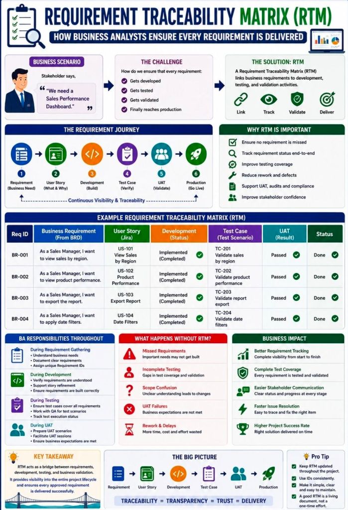
Requirements Traceability Matrix RTM & Business Analyst BA
A Requirements Traceability Matrix (RTM) is a structured project management document that links user and stakeholder requirements directly to their corresponding design elements, development deliverables, and verification test cases.
Acting as a living checklist throughout the project life cycle, its primary purpose is to ensure 100% test coverage, validate that all client requests are fulfilled, and prevent scope creep by identifying undocumented work.
The visual layout of a typical RTM template maps individual requirement rows against critical validation milestones.
🔄 Three Main Types of Traceability
The configuration of an RTM depends heavily on the direction of tracking needed for the project:
Forward Traceability: Tracks requirements forward into design, code, and test cases. It ensures the project executes every requested feature and that nothing gets left behind.
Backward (Backward-Looking) Traceability: Traces test cases and final deliverables back to the original requirement. It checks for scope creep, confirming that no extra, unauthorized features were added.
Bidirectional Traceability: Combines both approaches. It links requirements from origin to destination and vice versa, providing clear visibility during change management or troubleshooting.
📋 Structured Breakdown of RTM Content
A standard RTM is formatted as a multidimensional table. Below is the foundational structure, broken down into its logical data components:
1. Core Requirement Parameters
Requirement ID: A distinct alphanumeric identifier (e.g., REQ-001, BRD-102) for quick cross-referencing.
Requirement Type: Classifies the item (e.g., Business, Functional, Technical, UI, Security, or Regulatory Compliance).
Requirement Description: A concise textual explanation defining exactly what the feature or system must achieve.
Source/Origin: The document, stakeholder, client request, or meeting minutes where the requirement originated.
Priority Level: The urgency ranking of the item, usually categorized as High, Medium, or Low (or via MoSCoW ranking).
2. Design and Development Artifacts
Functional Specification ID: Links the requirement to the specific section of the functional design document.
Technical Design/Architecture Module: Points to the code packages, database tables, or system architectural components implementing the requirement.
3. Verification & Validation (Testing) Data
Test Case ID: The unique ID of the specific test cases designed to validate the feature (e.g., TC-101, TC-102).
Test Case Description/Objective: A snapshot of what the test case actually checks.
User Acceptance Testing (UAT) ID: Specific ID linking to end-user validation scenarios.
4. Execution & Quality Control Tracking
Test Execution Status: The real-time health indicator of the testing suite (e.g., Passed, Failed, Blocked, Not Run).
Defect/Bug ID: If a test fails, this column logs the active issue tracker ID (e.g., Jira ticket BUG-404) linked to the breakdown.
Current Deployment Status: Defines the project readiness stage (e.g., In Progress, Dev, QA, Production).
💡 Core Benefits of Maintaining an RTM
Prevents Missed Features: Verifies that every business requirement translates into clean code and valid testing cycles before software deployment.
Streamlines Change Management: If a client alters a feature, developers can quickly scan the RTM row to see exactly which code modules and test scripts need updates.
Simplifies Compliance Audits: Serves as regulatory proof in safety-critical landscapes (like medical devices or automotive software) that every target function passed validation.
Requirements Traceability Matrix RTM & Business Analyst BA
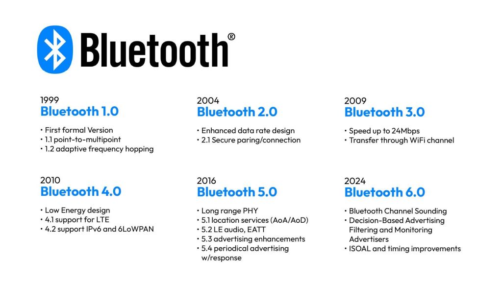
Bluetooth is a universal, short-range wireless communication standard that enables electronic devices to exchange data and audio over ultra-high frequency (UHF) radio waves (operating between 2.402 GHz and 2.480 GHz). It forms localized, temporary networks known as piconets to seamlessly bridge data gaps without the clutter of physical wires or cables.
To combat signal congestion in the crowded 2.4 GHz band—which it shares with Wi-Fi and microwaves—Bluetooth uses a technique called Adaptive Frequency Hopping (AFH), rapidly switching between 79 or 40 channels up to 1,600 times per second to maintain a stable, secure connection.
Named by Intel engineer Jim Kardach after the 10th-century Scandinavian King Harald “Bluetooth” Gormsson—who famously united warring Danish tribes into a single kingdom—the technology was built to similarly unify incompatible PC, cellular, and digital device ecosystems. The iconic Bluetooth logo is a direct nod to this heritage, fusing the ancient Norse runes ᚼ (Hagall) and ᛒ (Bjarkan) representing King Harald’s initials.
Bluetooth Overview and Detailed Chronological Timeline
🏛️ Era 1: Pre-Commercialization & Foundation (1989–1998)
Before becoming an open global standard, Bluetooth began as a proprietary corporate feasibility project aimed at liberating electronics from restrictive RS-232 data cables.
1989: Nils Rydbeck (CTO of Ericsson Mobile) and inventor Johan Ullman initiate a “short-link” radio technology project designed to develop comfortable wireless headsets.
1994: Jaap Haartsen and Sven Mattisson are tasked by Ericsson leadership to formally design the hardware infrastructure in Lund, Sweden. They focus on low-power, low-cost radio architectures.
1997: The engineering team achieves a functional, workable link layer solution. Intel’s Jim Kardach proposes the temporary codename “Bluetooth”.
1998: Recognizing a global framework requires cross-industry alignment, Ericsson joins forces with IBM, Intel, Nokia, and Toshiba to found the Bluetooth Special Interest Group (SIG) to establish an open, license-free standard.
📱 Era 2: The Classic Bluetooth Era (1999–2009)
The first commercial implementation focused heavily on replacing peripheral wires. However, early builds struggled with device-role conflicts, high power consumption, and severe data limitations.
1999 (v1.0 & v1.0b): The Bluetooth SIG publishes the official Bluetooth 1.0 specification. It is heavily plagued by interoperability issues and mandatory hardware address exposure, creating distinct privacy gaps.
2001 (v1.1): Standardized globally under the IEEE 802.15.1 banner. Fixes version 1.0 connection bugs, supports point-to-multipoint slave connections, and introduces unencrypted channel support. The Sony Ericsson T36 debuts as the first commercial phone with integrated Bluetooth.
2003 (v1.2): Introduces Adaptive Frequency Hopping (AFH) to stop Wi-Fi network interference. Adds Extended Synchronous Connections (eSCO) to rescue voice audio quality by allowing packet retransmissions.
2004 (v2.0 + EDR): Unleashes Enhanced Data Rate (EDR). Maximum throughput leaps from a nominal 721 kbps to 3 Mbps, greatly reducing power draw through shorter transmission cycles.
2007 (v2.1 + EDR): Introduces Secure Simple Pairing (SSP). This eliminates complex PIN-code handshakes, improving device security while seamlessly supporting Near Field Communication (NFC) proximity pairings.
2009 (v3.0 + HS): Debuts High Speed (HS) architecture. It uses a clever dual-radio configuration where Bluetooth creates the initial handshake, but offloads large media payloads to an internal 802.11 Wi-Fi link for speeds up to 24 Mbps.
🔋 Era 3: The Bluetooth Low Energy (BLE) & IoT Era (2010–2015)
Prior versions consumed too much power for miniature electronic applications. This era redefined the standard, establishing an entirely separate protocol tier optimized to run on tiny coin-cell batteries for the burgeoning Internet of Things (IoT) market.
2010 (v4.0): The pivotal launch of Bluetooth Low Energy (BLE) (branded initially as Bluetooth Smart). Devices can remain asleep until data bursts happen, drastically dropping baseline energy consumption.
2013 (v4.1): Engineers adjust software layers to prevent direct frequency collision with 4G LTE bands. Devices can now act as both an independent hub and peripheral sensor simultaneously.
2014 (v4.2): Designed entirely for smart home architecture, this update adds support for IPv6 and 6LoWPAN. This allows smart sensors to connect directly to the internet without intermediary mobile gateways.
🌐 Era 4: High-Performance & High-Precision Mesh Era (2016–Present)
Modern iterations have fundamentally transformed the technology from a basic local data-link pipe into a highly robust, secure mesh network and precision spatial positioning framework.
2016 (v5.0): Doubles BLE transmission speeds to 2 Mbps and quadruples operational range up to 240 metres. It optimizes performance for large-scale smart homes and multi-room layouts.
2019 (v5.1): Introduces Direction Finding via Angle of Arrival (AoA) and Angle of Departure (AoD) antennae arrays. Devices achieve hyper-local indoor positioning down to centimeter-level accuracy.
2020 (v5.2): Unveils LE Audio running over the highly efficient LC3 Codec. It introduces Auracast, which enables a single source device to stream high-fidelity audio to an infinite number of nearby headphones or hearing aids.
2021 (v5.3): Adds connection subrating to reduce communication switching latencies. Improves peripheral device power optimization and encryption control keys.
2023 (v5.4): Adds Periodic Advertising with Responses (PAwR) alongside Encrypted Advertising Data (EAD). This allows two-way secure mass communication, tailored specifically for thousands of commercial electronic shelf labels.
2024 (v6.0): Incorporates groundbreaking Channel Sounding technology. It employs phase-based time-of-flight measurements to provide centimeter-level distance awareness, creating incredibly secure digital car and home keys that prevent relay signal tracking attacks.
Bluetooth Overview and Detailed Chronological Timeline
HPE NonStop Pathway is a premier transaction processing and application server environment (TS/MP) that powers mission-critical Online Transaction Processing (OLTP). It handles critical application services—such as fault tolerance, load balancing, memory management, and process scheduling—automatically, allowing developers to focus strictly on business logic.
HPE NonStop Pathway is a transaction processing & application server environment (TS/MP)
Detailed Timeline Breakdown
The history and evolution of the Tandem NonStop platform and its Pathway environment span decades of architectural transformations and corporate ownership, categorized by distinct hardware and software eras:
1. The Tandem Era (1974–1997)
1974: Tandem Computers Inc. is founded by Jimmy Treybig to build the first fault-tolerant commercial hardware.
1976: The first Tandem NonStop system (NSI) is launched. Early apps had to be manually coded for fault tolerance.
1981: NonStop II is released, bringing 32-bit addressing.
1983: The Transaction Monitoring Facility (TMF) is introduced. Together with the launch of the Pathway transaction management software, the need for programmers to write manual fault-tolerance logic into their code is officially eliminated.
1986: Tandem releases the EXT as an entry-level system, followed by the VLX.
1991: Tandem introduces the Cyclone/R and initiates a massive architectural shift away from proprietary stack machines towards MIPS RISC processors.
1997: Compaq acquires Tandem Computers, placing the NonStop product line under its umbrella.
2. The Compaq & Early HP Era (1997–2014)
2001–2002: Hewlett-Packard (HP) merges with Compaq. The platform is rebranded as HP NonStop.
2005: The HP Integrity NonStop (TNS/E) series is introduced, migrating the fault-tolerant platform to Intel Itanium microprocessors. Pathway continues to be the main driver for high-volume banking and telecom applications.
2011: Further hardware advancements lead to the release of HP Integrity NonStop BladeSystems.
3. The Modern HPE Era (2015–Present)
2015: Hewlett-Packard splits, and the NonStop environment transitions to Hewlett Packard Enterprise (HPE).
2015/2016: Introduction of NonStop X (TNS/X) systems, marking the platform’s migration to standard Intel x86-64 processors and adopting InfiniBand interconnects. Pathway capabilities are updated to span dynamic server classes across multiple systems (Pathway Domains).
Present: HPE continues to modernize the NonStop architecture, integrating the platform with HPE GreenLake for consumption-based models and providing native support for modern DevOps tools and hybrid cloud deployments.
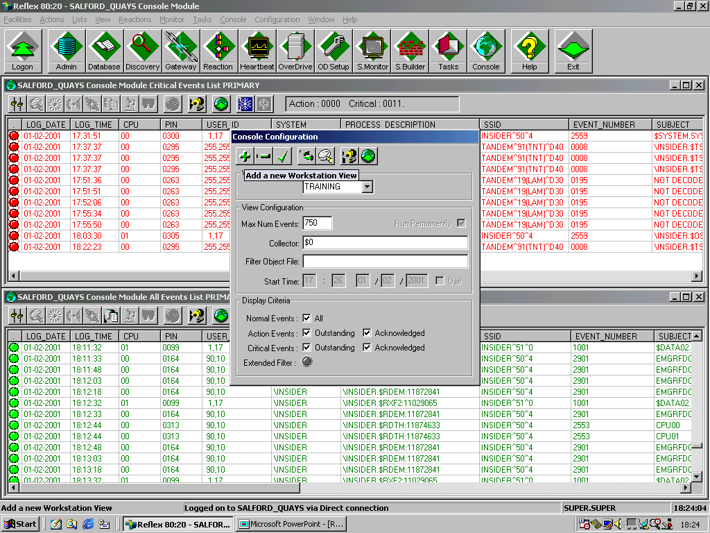
In the HPE NonStop ecosystem, EMS (Event Management Service) is the core software subsystem responsible for collecting, formatting, filtering, logging, and routing system and application event messages. It provides fault-tolerant monitoring by gathering data from EMS collectors and selectively delivering alerts to consoles, log files, or automated management applications.
The evolution and detailed historical timeline of NonStop EMS events and architecture is broken down by era below:
1. The Tandem Guardian Era (Late 1970s – 1980s)
Focus: Foundation of Fault-Tolerant Event Logging
1976: Tandem releases the original Tandem/16 (NonStop I) system. Early event handling was primarily a rudimentary terminal console logging process.
1978: System administrators struggled with message scaling as clusters and terminal networks expanded. Tandem began developing structured event tracking, paving the way for standardized subsystem messages.
1980s: Introduction of early message formatting. Event messages 1 through 511 were reserved for unformatted, raw console events. The Event Management Service (EMS) was gradually formalized to centralize scattered terminal messages.
2. The D-Series & TMF Era (1990s)
Focus: Distributed Management & The Birth of Modern EMS
1991: Tandem releases the Cyclone/R (CLX/R) and later the Himalaya K-series using MIPS processors.
1993: The publication of the seminal EMS Reference Summaries standardized EMS APIs and SPI (System Programming Interface). Event IDs were structured into standardized subsystems (e.g., negative-numbered kernel messages).
1995: The NonStop Kernel introduced Open System Services (OSS), natively integrating Unix-like event logs into the Guardian architecture.
1997: Compaq acquires Tandem Computers. EMS underwent significant rewrites to interface with remote servers and client networks. The S-Series was launched utilizing ServerNet fabric, introducing advanced, distributed event collectors and distributors.
3. The Compaq Transition & HP Integration (2000s)
Focus: Web-Based Management and Automation
2000 – 2003: Legacy ViewPoint tools were expanded. The emergence of GUI interfaces and DSM/PM (Distributed Systems Management/Performance Monitor) allowed operators to browse and filter EMS logs on alternate/primary event files.
2003 – 2005: The transition to Web ViewPoint commenced, turning text-based EMS event logs into interactive, web-based graphical operations interfaces.
2006 – 2009: With HP fully in charge after merging with Compaq, EMS event viewing was modernized through TSM (Tandem/HP Systems Management) and the Open System Management (OSM) Event Viewer.
2015 – 2017: The platform is rebranded as HPE NonStop as the architecture migrates to x86 processors. EMS systems are upgraded to handle large datasets, feeding complex event processing (CEP) and SNMP trap frameworks for modern data centers.
2018 – 2023: HPE integrates NonStop systems with HPE GreenLake. EMS event logging is modernized with API-driven integrations, allowing system events to be consumed by off-platform enterprise loggers, Splunk, and cloud-management consoles.
2024 – 2026: EMS events operate in highly virtualized and hybrid cloud (x86 and Virtual NonStop) environments. Event management heavily relies on modern distributed systems where EMS distributors push logs seamlessly into centralized IT monitoring suites and continuous availability dashboards.
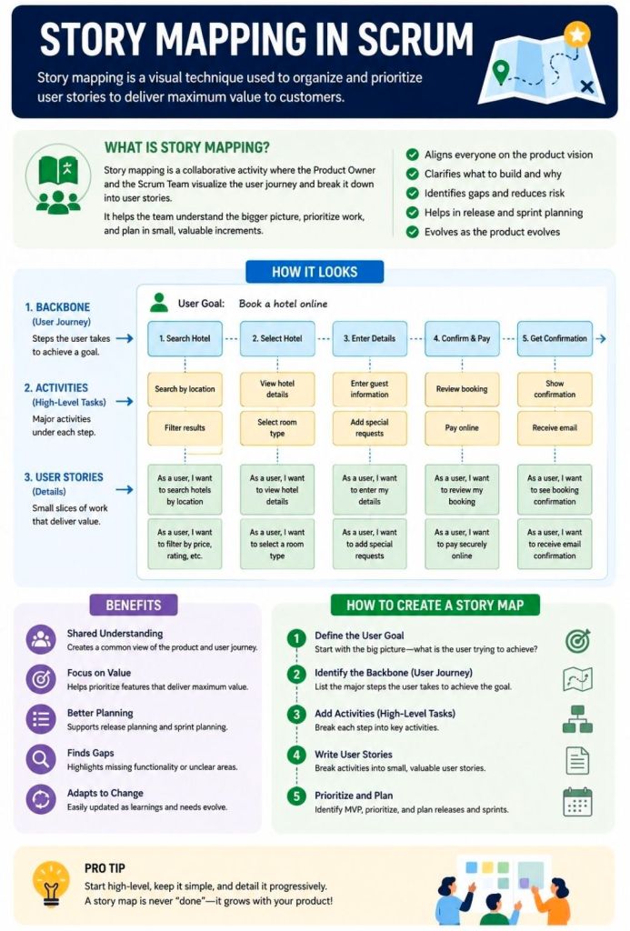
Story Mapping in Agile and Scrum is a visual technique that organizes user stories along a chronological user journey. It helps teams see the big picture, avoid flat, disconnected backlogs, and collaborate on planning iterative releases that consistently deliver user value.
How a Story Map is Structured
A story map is a two-dimensional grid—often built with sticky notes on a whiteboard or via software like Miro or Visual Paradigm. It breaks work down into three levels of hierarchy:
Horizontal Axis (The Spine): Arranges the customer journey chronologically.
Activities: The broadest goals a user wants to achieve (e.g., “Checkout”).
Steps: The specific tasks required to complete the activity (e.g., “Enter Shipping Info,” “Pay”).
Vertical Axis (Details & Priority): Stacks beneath each step are the detailed user stories, epics, or features. They are organized by priority, with the most critical or highly sophisticated tasks at the top.
The Benefits of Story Mapping
Teams use this technique—popularized by Jeff Patton—to achieve several core Agile goals:
Prevents “Flat Backlog” Blindness: Gives stakeholders and developers a birds-eye view of how the entire application or feature fits together.
Defines the MVP: Allows teams to draw horizontal “release lines” across the map. The items sitting above this line form the barebones “walking skeleton” or Minimum Viable Product (MVP).
Aids Sprint Planning: Helps the Product Owner pull well-sequenced, context-aware stories directly into sprint backlogs.
Fosters Collaboration: Moves the team away from siloed requirement docs and toward collaborative conversations around actual user behavior.
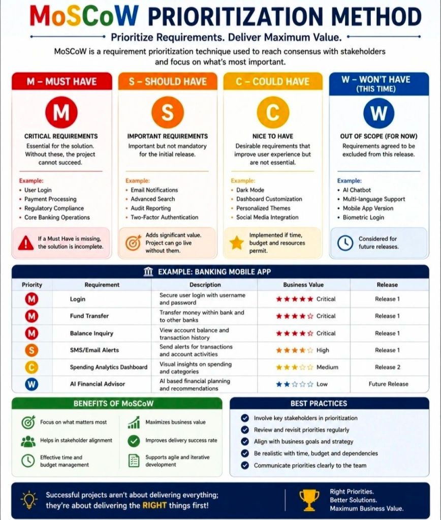
The MoSCoW method is a popular requirements prioritization technique used in project management and software development to help stakeholders reach a common understanding on the importance of deliverables. It categorizes tasks into Must, Should, Could, and Won’t have.
The MoSCoW Categories
Must Have: Non-negotiable requirements that are critical for success, compliance, or safety. Without these, the project is considered a failure and cannot be deployed.
Should Have: High-priority, important features that add significant value but are not strictly vital for immediate delivery. These are generally included if time permits, or they may have a manual workaround.
Could Have: Desirable, “nice-to-have” features that are small and easy to implement. These improve user experience but can be deferred or dropped without impacting the project’s overall success.
Won’t Have (or Won’t Have this time): Features that have been mutually agreed upon as out-of-scope for the current release or timeframe. They are deliberately excluded to prevent scope creep, though they may be added to the backlog for future cycles.
Why and When to Use It
Resource Management: It helps maximize limited time, budget, and resources by focusing effort on the features that provide the most immediate ROI.
Stakeholder Alignment: It acts as a negotiation tool, forcing stakeholders to agree on what is genuinely critical versus what is purely desirable.
Agile Environments: It is a foundational practice in Agile frameworks like DSDM, where teams adhere to fixed deadlines (timeboxes) and adjust the project scope instead.
Best Practices for Implementation
The 60-20-20 Rule: A common best practice is to ensure that Must Haves consume no more than 60% of the team’s total effort. Roughly 20% should be allocated to Should Haves, and 20% reserved for Could Haves to act as contingency room.
Challenge Assumptions: When classifying a requirement as a Must, ask: “What happens if we don’t do this? Can we still deploy the product?” If the project can still function—even awkwardly—it is likely a Should or Could.
Continuous Review: Priorities aren’t static. Re-evaluate your MoSCoW list at the end of every sprint or development cycle, as a Could Have from a previous phase might be upgraded or permanently discarded.
The eBUG (European BASE24 User Group) Conference is the premier annual gathering for financial institutions, retail banking professionals, and technical architects utilizing ACI Worldwide’s foundational retail payment engine, BASE24 and BASE24-eps.
Operating alongside global HPE NonStop hardware environments, the conference traditionally functions as a collaborative technical focus group (TFG) and customer roundtable. It brings together industry experts to address mission-critical transaction switching, regulatory compliance mandates, payment security architectures, and core software migrations.
Detailed Era Breakdown & Timeline
Era 1: The Classic BASE24 & ITUG Tandem Era (1980s – Late 1990s)
Focus: Evolution of core ATM/POS switching on Tandem (HPE NonStop) platforms, localized compliance, and basic card processing networks.
1982–1985: The birth of the early European user networks following the launch of BASE24 software by Applied Communications Inc. (now ACI Worldwide). Early meetings are heavily dependent on regional vendor user group support.
1992: Initial formations of explicit regional sub-committees under the International Tandem User Group (ITUG). The European base of users establishes formal communication pipelines.
1996: Increased focus on the early adoption of regional card mandates, standardising early transaction switching over X.25 networks, and prepping mainframe systems for high-availability roundups.
1999: A definitive milestone focused on Y2K compliance readiness. Conferences during this era are heavily centered on stress-testing legacy BASE24 code blocks, ensuring clock dates rollover flawlessly across financial networks without disrupting global merchant processing.
Era 2: The EMV Mandate & “Classic-to-EPS” Transition Era (2000 – 2010)
Focus: Overhauling core code for Chip & PIN (EMV) regulations, migrating toward open system frameworks, and introducing the next-generation BASE24-eps payment platform.
2003:The EMV Blueprint Era. The conference takes a primary steering role for European banks facing strict Eurocard, Mastercard, and Visa (EMV) liabilities. User sessions heavily focus on updating terminal messaging scripts.
2005: Introduction of BASE24-eps to the wider user group community. Discussions shift away from the classic architecture toward modern open-systems deployments, leveraging UNIX, Linux, and IBM z/OS alongside traditional NonStop environments.
2007 (Istanbul, Turkey): The group expands geographic footprints into the borders of Europe and Asia. Themes heavily stress global interoperability, cross-border transactional routing, and real-time fraud monitoring.
2008 (Vienna, Austria): High-water mark for attendance during the mid-2000s. Presentations focus on deep-dive technical configurations of BASE24-eps Release 08.2, service-oriented architecture (SOA) wrappers, and high-availability testing matrices.
2009 (Prague, Czech Republic): Real-time monitoring tools become a central talking point. Despite global financial pressures, the user community explicitly defends the strength of HPE NonStop infrastructure for running foundational retail networks.
Era 3: Security Hardening & The Independent Pivot Era (2011 – 2018)
Focus: Adapting payment loops to rigid PCI-DSS requirements, cloud capability tracking, and shifting the conference structure to independent consulting sponsorships.
2011: Focus turns squarely onto PCI-DSS Compliance and tokenisation. Roundtables detail architectural techniques to secure transaction journals, encrypt key lines, and prevent man-in-the-middle exploits at the ATM level.
2012 (London, UK): Held at the historic Trinity House near Tower Bridge, this event marks a structural pivot. Moving away from a pure ACI-hosted workspace, independent payment consultancies (such as PayX) drive user discussions. This Technical Focus Group explicitly evaluates the limits of legacy systems against “intelligent” multi-vendor ATM software.
2015: Immediate focus addresses the challenges of Real-Time / Instant Payments mandates across the Eurozone. Systems engineers share optimization scripting paradigms to support sub-second processing SLA ceilings.
2018: The rise of Open Banking / PSD2 Regulations. Technical breakout sessions outline how to safely open classic BASE24 architectures to third-party APIs through microservices wrappers and middleware adapters without breaking strict system uptime criteria.
Era 4: Modernisation & Cloud-Native Coexistence Era (2019 – Present)
Focus: ISO 20022 message standard migrations, cloud-native deployments, and containerization strategies.
2020–2022: Transition to hybrid tracking methodologies due to travel constraints. The baseline focus targets data integration, remote system management, and virtualized system-hardening techniques.
2023–2024:The ISO 20022 Mandate. Sessions are dominated by the industry-wide migration from legacy ISO 8583 message lines to the XML-based ISO 20022 financial standard. Systems architects present automated script parsers to translate real-time payment formats across legacy logic systems.
2025–2026: Integration of Cloud-Native BASE24-eps architectures. Contemporary meetups explore containerized execution patterns, utilizing AI models within the authorization loop to spot edge-case fraud patterns in real-time, and evaluating long-term roadmaps for hardware-security modules (HSMs).
eBUG (European BASE24 User Group) Conference Overview and Chronological Timeline
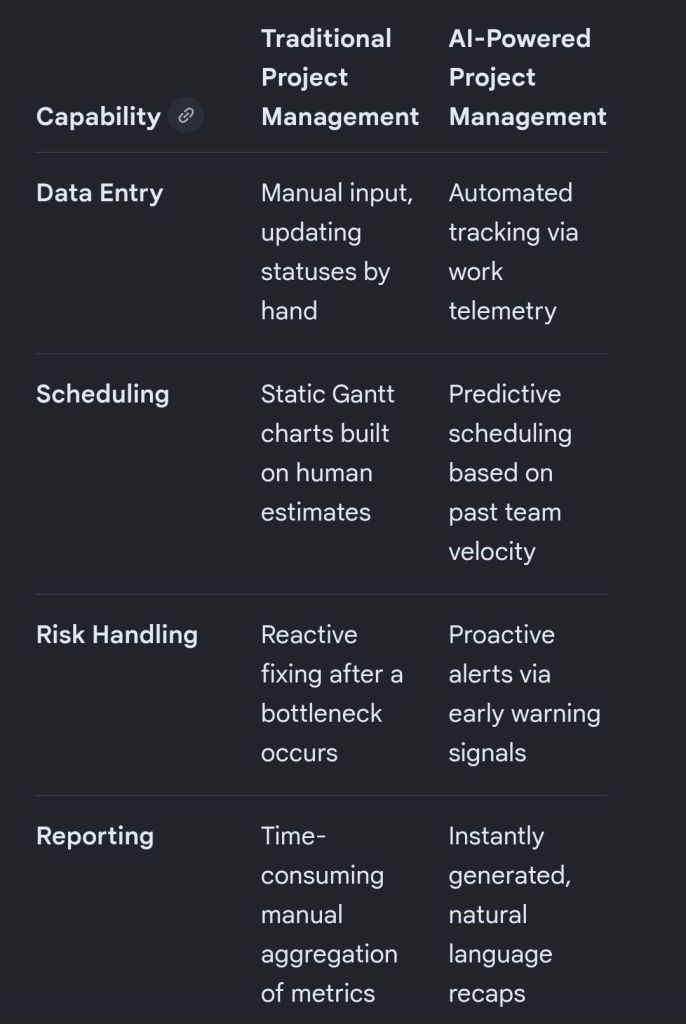
Artificial intelligence is transforming project management by shifting software from passive data repositories into active, predictive engines that automate tedious administration and improve decision accuracy.
The breakdown below covers the primary AI approaches and the specific tools driving each function.
🧠 Core AI Approaches in Project Management
Rather than basic, rule-based automation (“if X happens, do Y”), true AI uses model-driven machine learning, natural language processing (NLP), and predictive analytics.
Predictive Analytics & Forecasting: Machine learning models evaluate past team velocity, budget trends, and historical timelines to forecast delays and cost overruns before they occur.
Natural Language Processing (NLP): Large Language Models (LLMs) digest unstructured data like unstructured chats, customer emails, and meeting transcripts to extract action items, drafting project updates automatically.
Resource Optimisation: Algorithms match team members’ skills, existing workloads, and availability with upcoming project requirements to distribute work sustainably and efficiently.
Proactive Risk & Scope Creep Detection: AI monitors real-time activity and flags deviations from the initial project charter, alerting teams to emerging bottlenecks.
🛠️ AI Project Management Tools Broken Down by Use Case
1. All-in-One Work Operating Systems (Work OS)
These comprehensive platforms integrate AI deeply into everyday task tracking, workflows, and communication.
Monday.com: Features an integrated AI Assistant that auto-generates task descriptions, brainstorms project ideas, and summarizes long activity threads across cross-functional workspaces.
ClickUp: Uses its unified “ClickUp Brain” engine to break down major project milestones into contextual subtasks, answer project-related queries instantly, and write status updates.
Asana: Leverages AI smart agents to recommend task assignments, identify workflow blockers early, and suggest ideal task prioritisation based on team capacity.
Wrike: Focuses heavily on predictive analytics and intelligent insights, allowing larger organisations to move past traditional tracking into data-driven risk monitoring.
2. Meeting & Communication Intelligence
These tools alleviate the administrative burden of manually taking notes, tracking ownership, and summarizing align-meetings.
Otter.ai: Transcribes team calls in real time and automatically creates bullet-point action items, keyword summaries, and structured meeting recaps.
Microsoft Copilot / Google Gemini: Seamlessly pulls historical data from your workspace ecosystem (emails, documents, calendars) to draft project charters or assemble stakeholder reports with minimal context.
3. Engineering & Agile Backlog Management
Built to address the rapid velocity changes and technical needs of software development teams.
Jira (Atlassian Rovo): Uses built-in AI agents to organize bloated backlogs, surface conflicting dependencies, and estimate how long features will take based on historical sprint velocities.
4. Document & Knowledge Management
Designed for centralizing organizational resources so teams don’t waste time hunting for internal data.
Notion AI: Acts as a central, conversational wiki workspace that synthesizes notes, translates documents, drafts release notes, and surfaces data buried in complex project databases.
NotebookLM: A powerful, localized research assistant that organizes complex internal project documentation, creates study guides for teams, and answers cross-document queries accurately.
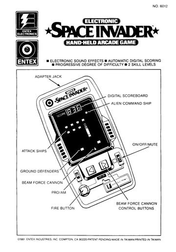
The Entex Space Invader handheld electronic game is a classic VHF-style portable arcade unit released in 1980. It is highly sought after by collectors of vintage 1980s electronics. I used to have one in the early eighties, my first taste of computing technology and gaming.
Design & Hardware
Entex Space Invader handheld electronic game
Form Factor: Large wedge-shaped black plastic tabletop/handheld console designed by Entex Tokyo.
Objective: Move your laser cannon horizontally across the bottom of the screen to shoot down descending waves of alien invaders.
Layout: Displays four distinct lanes of action with columns of moving digital alien targets.
Scoring System: Tracks and displays electronic numeric scoring up to a maximum of 1,000 points.
Audio: Features simple built-in, synthesized electronic space sound effects for firing lasers and alien tracking.
Known Product Variants
1980 Black Model: The original release featuring a dark case, designed and programmed natively in Japan by Entex Tokyo.
1981 Grey Model: A re-programmed version developed by Rick Dyer & AMS featuring slightly adjusted gameplay. The distinct grey casing was actually the result of a factory paperwork typo that swapped two Pantone color codes.
Entex Space Invader handheld electronic game, back of box
The Project Management Templates by Mark Whitfield constitute a comprehensive toolkit of over 200 editable resources designed to accelerate project delivery across Agile, Waterfall, and PRINCE2 frameworks.
The structural breakdown of the core templates is organised by functional category, specific template, integrated Microsoft Office tool, and operational description:
1. Project Planning & Scheduling
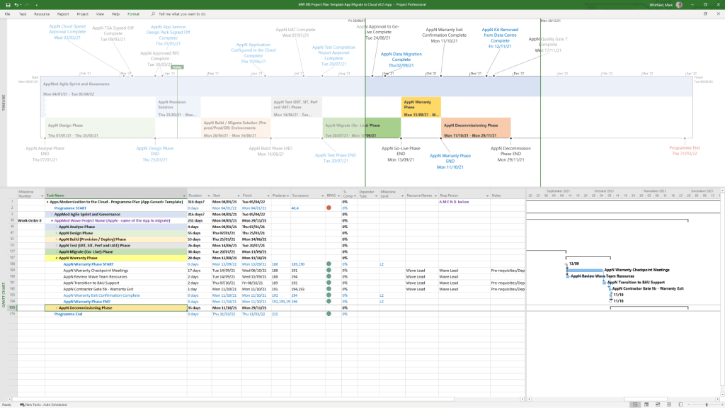
Detailed SDLC Project Plan
MS Tool: Microsoft Project (.mpp)
Description: A master schedule structured around the Software Development Lifecycle (SDLC) from development through testing, deployment, and Early Live Support (ELS), easily toggled between Agile Scrum and traditional Waterfall.
PRINCE2 7th Edition Project Plan
MS Tool: Microsoft Project (.mpp) & MS Excel (.xlsm)
Description: Fully annotated task list aligned with the 7th edition principles, colour-coded by activity type (blue for artifact creation, brown for management decisions, purple for updates).
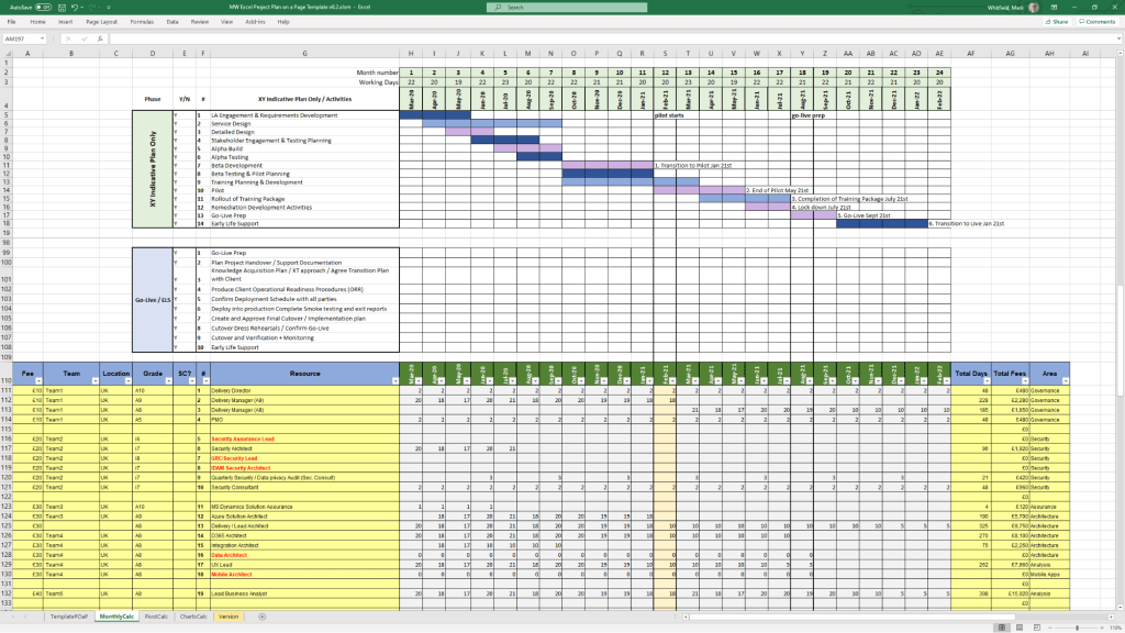
Detailed Waterfall Project Planner
MS Tool: MS Excel
Description: A portable, license-free alternative to MS Project featuring baseline versus forecast tracking, an integrated Gantt chart view, and automated progress charts.
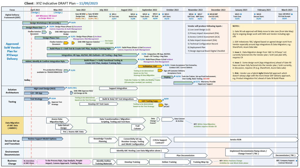
Plan on a Page (POaP)
MS Tool: MS PowerPoint & MS Excel
Description: High-level, executive-ready roadmaps containing over 30 slide variations used to communicate project timelines, key milestones, and work streams to senior stakeholders.
1. Project Planning & Scheduling POAP MS PowerPoint Templates2. Project Planning & Scheduling MS Project Templates3. Project Planning & Scheduling MS Excel Templates
2. Operational Control & Governance
Comprehensive RAID Log & Charts
MS Tool: MS Excel
Description: A highly detailed central registry featuring distinct tabs to track Risks, Actions, Issues, Opportunities, Dependencies, Lessons Learned, and Change Requests alongside visual metric dashboards.
Basic RAIDs Tracker
MS Tool: MS Excel
Description: A scaled-down, simplified version of the master RAID log optimized for quick turnarounds, minor bids, and low-complexity projects.
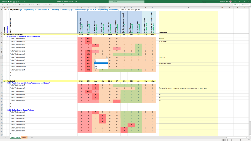
RACI Matrix
MS Tool: MS Excel
Description: A governance sheet mapping project deliverables against specific team roles to clarify who is Responsible, Accountable, Consulted, and Informed.
Agile Story Dependency Tracker
MS Tool: MS Excel
Description: A specialised log to document and track blocker stories tied to external suppliers or client-side dependencies that risk driving scope changes.
1. Operational Control & Governance MS Excel RACI Template
3. Financial & Resource Management
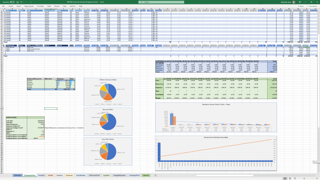
Project Financial Tracker
MS Tool: MS Excel
Description: A financial controller mapping internal and external forecast costs against actuals, factoring in margins, variances, supplier fees, and expense categories.
Resource, Sickness, & Leave Tracker
MS Tool: MS Excel
Description: An operational matrix monitoring annual leave, sickness, and training schedules to adjust resource availability and capacity within the master schedule.
1. Financial & Resource Management MS Excel Templates
4. Agile Delivery Metrics
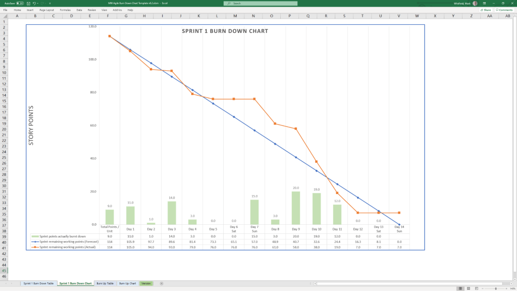
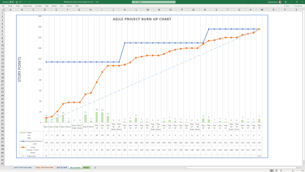
Agile Burn Down & Burn Up Charts
MS Tool: MS Excel
Description: Manual data-table tracking solutions designed to visualise sprint or release velocity for teams operating without access to enterprise tools like Jira.
1. Agile Burn Down Chart in MS Excel Template Example2. Agile Burn Up Chart in MS Excel Template Example
5. Communications & Administration
PRINCE2 Management Products
MS Tool: MS Word (.doc)
Description: A full portfolio of standard documentation masters including Project Initiation Documents (PID), Project Briefs, Highlight Reports, and Business Cases.
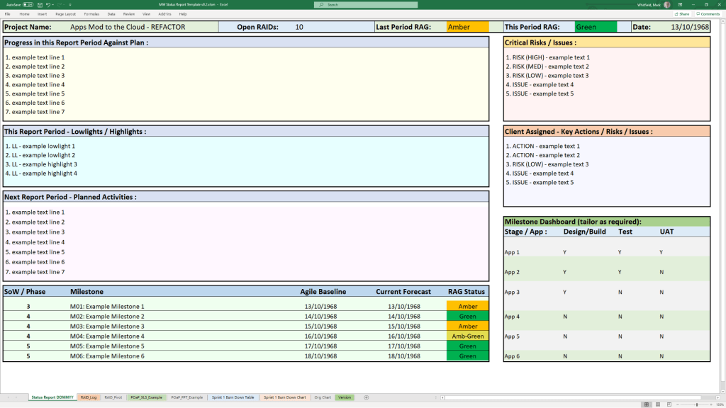
Project Status Report
MS Tool: MS Word & MS PowerPoint
Description: Weekly and monthly progress reporting templates featuring structured sections for milestones, blockers, financial status, and RAG indicators.
Kick-Off Deck & Mobilisation Kit
MS Tool: MS PowerPoint
Description: Onboarding and alignment slide decks designed to define scope, establish ground rules, and guide teams through project initiation.
Meeting Minutes Template
MS Tool: MS Word
Description: An action-oriented meeting layout tailored for capturing critical decisions, owners, and deadlines uniformly.
1. Communications & Administration MS Excel Status Report Template Example
The best approach to writing a project plan breakdown is to use a top-down decomposition strategy centered on a Work Breakdown Structure (WBS). This technique methodically slices a complex, high-level project into smaller, manageable chunks called work packages, ensuring that nothing is missed.
To build a flawless, actionable project breakdown, you must establish the project’s foundation before dissecting it into individual tasks.
1. Define the Scope and Deliverables
Before diving into a micro-level breakdown, you must know what you are building—and what you are not building.
Write a scope statement: Document the final outcomes, project boundaries, and explicit exclusions to prevent scope creep.
Identify major deliverables: Determine the high-level milestones or chunks of tangible value that must be completed.
Apply the 100% rule: The Project Management Institute (PMI) notes that your WBS must include 100% of the internal, external, and interim project management work.
2. Structure the Levels of Decomposition
A good project plan breakdown uses hierarchical tiers. Do not mix daily tasks with macro phases. Instead, follow a logical breakdown hierarchy:
Level 1 (The Project): The overall project objective or final product.
Level 2 (Phases or Major Deliverables): Broad operational segments (e.g., Initiation, Design, Development, Testing).
Level 3 (Sub-deliverables): Specific components within a phase (e.g., under Development, you might have Frontend Architecture).
Level 4 (Work Packages): The lowest level of the WBS. These are discrete items that can be assigned to a specific team or individual and estimated for time and budget.
3. Apply the 80-Hour Rule
When decomposing down to the task level, determine how granular you need to be by tracking effort, not just calendar time:
The 80-hour threshold: A single work package should take no more than 80 hours (two weeks of full-time work) and no less than 8 hours to complete.
Avoid micro-management: If a task takes less than 8 hours, group it with others. If it exceeds 80 hours, it is too complex and needs to be broken down further.
4. Build a WBS Dictionary
A visual chart or list is helpful, but context prevents mistakes. For each work package at the bottom of your hierarchy, document:
Task description: Clear language outlining what “done” actually looks like.
Assigned owner: One single person or team responsible for the execution.
Pre-requisites and dependencies: Clarify which tasks must finish before the next can begin.
5. Sequence, Estimate, and Schedule
Once the work is broken down, pull it into a working chronological timeline using software like Microsoft Project (see MS .mpp templates in website banner), Asana or Monday.com.
Sequence activities: Map the chronological order and identify the critical path—the longest string of dependent tasks.
Estimate duration & resources: Gather the actual people doing the work to estimate time, capacity, and material needs realistically.
Add contingency: Factor in safety buffers to protect the project baseline from unexpected delays.
Microsoft Project is a powerful project management software used to plan, schedule, and oversee tasks, resources, and deadlines. Its native .mpp file format supports building Work Breakdown Structures (WBS), calculating critical paths, allocating resources, and monitoring project budgets within the Microsoft ecosystem.
Configuring a high-quality .mpp plan requires a systematic approach to ensure schedule accuracy and prevent logic errors. Follow this step-by-step methodology to build a robust plan:
1. Project Initialization
Set Project Information: Go to the Project tab, click Project Information, and define your Start Date. Ensure the scheduling is set to start from this date rather than a “Current Date” override.
Define Working Calendars: Adjust your project’s default calendar for weekends, statutory holidays, and company non-working time so the timeline accurately reflects actual working days.
Configure Default Scheduling: Go to File > Options > Schedule and set New tasks created to Auto Schedule. This ensures your tasks respond automatically to changes in predecessors and durations.
2. Work Breakdown Structure (WBS)
Brainstorm Task Lists: Before entering dates, list all project deliverables and normal tasks in the Gantt Chart view.
Apply Hierarchy: Use the Indent/Outdent features to organize tasks into major phases (Summary Tasks) and actionable subtasks (Work Packages).
Create Milestones: Set the duration of key deliverable completions or approval gates to 0 days to act as clear checkpoints on your timeline.
3. Task Dependencies & Logic
Establish Relationships: Link tasks in logical sequences (e.g., using Finish-to-Start relationships). Every task—except the very first one in the project—must have a predecessor.
Never Link Summary Tasks: Only link the lowest-level subtasks. Linking summary task bars introduces circular logic errors and unpredictability.
Avoid Hard Constraints: Do not type specific dates into the Start/Finish columns unless absolutely mandatory. Doing so creates “Must Start On” constraints that break the critical path when upstream tasks are delayed.
4. Resource Allocation
Setup the Resource Sheet: Navigate to the Resource Sheet and add all resources required to do the work, defining their standard rates, maximum capacities (e.g., 100% availability), and calendars.
Assign Resources: Return to the Gantt Chart and assign specific work resources (people) to corresponding tasks. This helps Microsoft Project calculate total effort and spot resource overallocations.
Resource Leveling: Use the built-in Resource Leveling feature to automatically adjust assignments and resolve conflicts when team members are overcommitted.
5. Finalizing and Tracking
Set a Baseline: Once the plan has been reviewed and approved by stakeholders, go to Project > Set Baseline. This captures a snapshot of your original scope, Start, Finish, Cost, and Work fields.
Set the Status Date: When recording progress, always set the Status Date to today’s date before entering percentage completions.
Project risks are uncertain events that, if they occur, can impact a project’s objectives. They are generally broken down into core categories: financial, technical, schedule, operational, and external. Proper risk assessment evaluates the probability and impact of these threats to prioritize mitigation strategies.
Detailed Risk Breakdown
1. Financial Risks
These risks relate to project budgets, funding cuts, and cash flow.
Cost Overruns: Expenses exceeding the allocated budget.
Funding Delays: Cash flow interruptions from sponsors or clients.
Currency Fluctuations: Affecting purchasing power for international materials.
Severity:High/Critical. Can lead to project cancellation if not mitigated.
2. Technical Risks
Emerging from technology gaps, security vulnerabilities, or poor integration.
Technology Failures: Systems crashing or underperforming.
Software Bugs: Errors causing glitches or data corruption.
Security Breaches: Data theft or loss compromising privacy.
Severity:Medium to High. Can completely stall deliverables or undermine final quality.
3. Operational Risks
Internal workflow inefficiencies, process breakdowns, and human factors.
Resource Shortages: Missing key team members or materials.
Poor Communication: Siloed workflows leading to rework and mistakes.
Supply Chain Disruptions: Delays in procuring high-quality goods.
Severity:Low to Medium. Tends to erode timelines quietly but can escalate if left unmanaged.
4. Schedule Risks
Risks jeopardizing deadlines, causing timeline slippage or severe delays.
Scope Creep: Uncontrolled changes or continuous addition of project requirements.
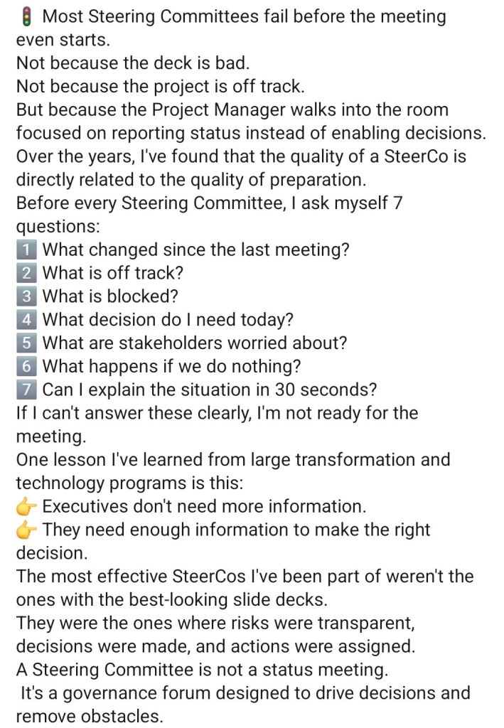
1. Preparing for a Steering Committee, SteerCo2. Preparing for a Steering Committee, SteerCo
Also,
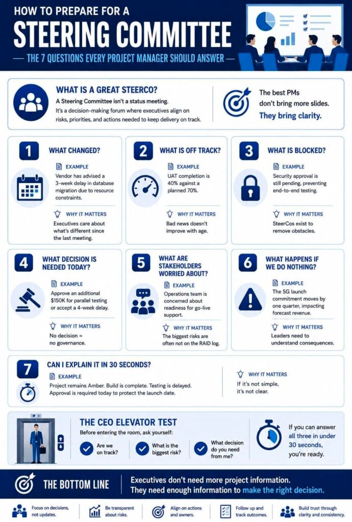
Preparing for a Steering Committee (SteerCo) means ensuring senior stakeholders are aligned, not surprised.
Share a concise pre-read 48–72 hours prior focusing on strategic updates, key risks, and necessary decisions. Use the meeting itself to seek guidance or arbitration rather than just reading through slides.
A successful SteerCo relies on keeping your presentation highly strategic. Here is an actionable checklist to prepare:
1. The Pre-Read (Distribute 2-3 Days Before)
One-Page Status Summary: A simple Red-Amber-Green (RAG) dashboard covering schedule, budget, and scope.
The “Ask”: Clearly outline the specific decisions or approvals you need from the committee.
No Surprises Rule: If there is a major blocker or budget overrun, brief key members individually before sending the formal pack.
2. The Presentation Structure
Executive Summary: Quick reminder of project goals, scope, and target timelines.
Project Progress: Highlight major milestones recently achieved.
Financial Health: Compare actual spend vs. planned budget.
Risks & Issues: Focus only on severe roadblocks and present actionable mitigation options.
Decisions Needed: State the options, pros/cons, and your recommendation.
3. During the Meeting
Focus on the Big Picture: Do not get bogged down in granular project details.
Manage the Politics: Be prepared for pushback and answer objectively. If you don’t know an answer, take an action item rather than bluffing.